使用EVE-NG模拟器,做思科的mplsxxx.为了复习路由协议,PE1-P-PE2间使用ISIS路由协议,PE-CE间分别使用静态、RIP、OSPF、BGP协议
实验:R4-R5间通过mplsxxx传输,R6-R7间通过mplsxxx
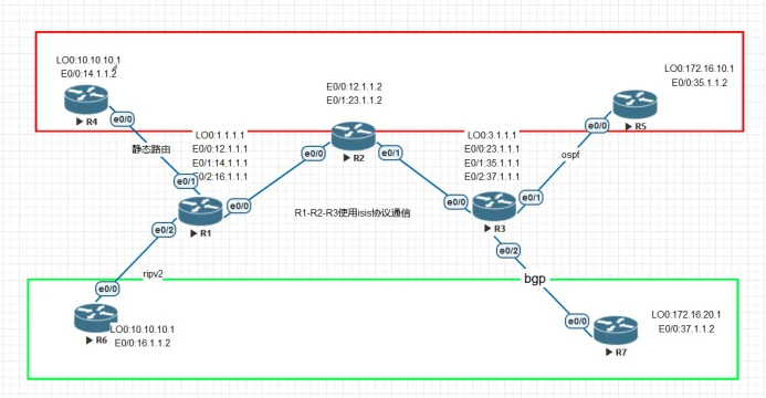
接口地址,路由协议配置如图
1、配置各路由器接口ip地址
2、ce设备正常配置,配置相应路由协议
3、pe1-p-pe2之间使用isis建立tcp连接
4、pe1-pe2间通过BGP建立内部BGP
5、pe上配置VRF,并应用到相应接口
6、配置PE-CE间的vrf路由协议,重发布MP-BGP协议
7、配置PE-PE间MP-BGP
8、分别在BGP-VRF中重发布到CE的路由协议,
拓扑:

*一、基础配置:根据拓扑图配置ip地址,PE-CE间的路由协议*
R4:CE1 模拟A公司一端
enable
conf t
hostname r4-ce1
line con 0
exec-t 0 0
exit
!配置接口地址
int lo 0
ip add 10.10.10.1 255.255.255.0
int e0/0
ip add 14.1.1.2 255.255.255.0
no sh
exit
!使用静态路由访问外网
ip route 0.0.0.0 0.0.0.0 14.1.1.1
======R6:CE2 模拟 B公司
enable
conf t
hostname r6-ce2
line con 0
exec-t 0 0
exit
int lo 0
ip add 10.10.10.1 255.255.255.0
int e0/0
ip add 16.1.1.2 255.255.255.0
no sh
exit
!作用ripv2协议与PE通信
router rip
ver 2
no auto-s
net 10.10.10.0
net 16.0.0.0
exit
==========R5:CE3
enable
conf t
hostname r5-ce3
line con 0
exec-t 0 0
exit
int lo 0
ip add 172.16.10.1 255.255.255.0
int e0/0
ip add 35.1.1.2 255.255.255.0
no sh
exit
router ospf 1
net 35.1.1.0 0.0.0.255 ar 1
net 172.16.10.0 0.0.0.255 ar 1
exit
=====r7-ce4
enable
conf t
hostname r7-ce4
line con 0
exec-t 0 0
exit
int lo 0
ip add 172.16.20.1 255.255.255.0
int e0/0
ip add 37.1.1.2 255.255.255.0
no sh
exit
router bgp 65501
nei 37.1.1.1 remote-as 100
network 37.1.1.0 mask 255.255.255.0
以上为四台mpls客户端的路由器配置,分别使用了静态、ripv2,ospf,bgp与运营商(pe)设备建立传输。可以看到客户端正常配置即可。可以将私网网段发送给PE设备
*二、PE1-P-PE2基础配置,包括,PE1–P-PE间使用isis协议建立TCP连接,PE1-PE2使用回环接口BGP建立邻居、PE1-P-PE2启用MPLS,使用标签来传递数据*
p-R2
enable
conf t
hostname r3-p
line con 0
exec-t 0 0
exit
ip cef :cisco开启快速转发功能(默认开启mpls)
mpls label protocol ldp !使用ldp协议自动分发标签
mpls label range 100 199 !设置自动分发的标签值 范围
int e0/0
ip add 12.1.1.2 255.255.255.0
mpls ip !接口模式启用mpls
no sh
int e0/1
ip add 23.1.1.2 255.255.255.0
mpls ip
no sh
exit
!配置isis协议
router isis
net 49.0001.0000.0000.0003.00
int e0/0
ip router isis
int e0/1
ip router isis
以上一段R2模拟P设备(运营商),开启mpls
=****=====以下配置为MPLS xxx核心配置****
*一、配置PE1-P-PE2间通过isis协议建立bgp关系,并使用mpls转发数据*
r1=pe1
enable
conf t
hostname r1-pe1
line con 0
exec-t 0 0
exit
int lo 0
ip add 1.1.1.1 255.255.255.255
int e0/0
ip add 12.1.1.1 255.255.255.0
no sh
exit
连接CE网的接口可先不配置,当配置完VRF以后,接口会初始化。
配置isis协议实现运营商设备的IGP互连,使回环接口可以互通,后面BGP要使用回环接口建立邻居
router isis
net 49.0001.0000.0000.0001.00
int e0/0
ip router isis
int lo 0
ip router isis
exit
!PE1-PE2间建立BGP
router bgp 100
nei 3.1.1.1 remote-as 100
nei 3.1.1.1 update-sou lo 0
Exit
!PE1-P-PE2间使用mpls转发数据,避免路由黑洞,这也是mplsxxx的外层标签
ip cef
mpls label protocol ldp
mpls label range 100 199
int e0/0
mpls ip
exit
==========r3=pe2
enable
conf t
hostname r3-pe2
line con 0
exec-t 0 0
exit
int lo 0
ip add 3.1.1.1 255.255.255.255
int e0/0
ip add 23.1.1.1 255.255.255.0
no sh
exit
连接内网的接口可先不配置,当配置完VRF以后,接口会初始化。
router isis
net 49.0001.0000.0000.0002.00
int e0/0
ip router isis
int lo 0
ip router isis
do sh ip route :查看路由表,pe1-pe2间回环接口建立tcp连接,为bgp做好准备
建立 bg邻居,并开户mpls
router bgp 100
nei 1.1.1.1 remote-as 100
nei 1.1.1.1 update-sou lo 0
Exit

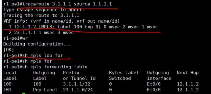
如图没有启用mpls时,数据的转发
mpls label protocol ldp
mpls label range 100 199
int e0/0
mpls ip
查,使用mpls实现转发
traceroute 3.1.1.1 source 1.1.1.1

启用了mpls后,可以看到通过标签进行转发数据依据
*分别在pe2,PE2上配置mpls xxx*
*一、VRF创建虚拟路由*
R1-PE1
ip vrf xxxa !创建一个名为xxxa的虚拟路由
rd 45:1 !创建RD,区分出不同的客户端
route-target export 100:1 !配置出方向RT值
route-target import 100:1
route-target both 100:1 !如果入出方向一样,以上两条可以写成一条
exit
!为B公司创建一个VRF
ip vrf xxxb
rd 67:1
route-target export 200:1
route-target import 200:1
exit
*二、为A客户端创建虚拟路由的静态路由*
ip route vrf xxxa 10.10.10.0 255.255.255.0 14.1.1.2
*为客户端B创建rip的虚拟路由*
router rip
version 2
address-family ipv4 vrf xxxb
network 16.0.0.0
no auto-summary
*三、将虚拟路由分别应用到相应接口,一定先关联vrf再配置ip*
interface Ethernet0/1
ip vrf forwarding xxxa
ip address 14.1.1.1 255.255.255.0
interface Ethernet0/2
ip vrf forwarding xxxb
ip address 16.1.1.1 255.255.255.0
测试:在Pe设备上–ping vrf xxxa 10.10.10.1
R3-PE2配置类似,rd可以不与对端一样,rt值对就即可
ip vrf xxxa
rd 45:1
route-target export 100:1
route-target import 100:1
exit
ip vrf xxxb
rd 67:1
route-target export 200:1
route-target import 200:1
exit
interface Ethernet0/1
ip vrf forwarding xxxa
ip address 35.1.1.1 255.255.255.0
no sh
Interface Ethernet0/2
ip vrf forwarding xxxb
ip address 37.1.1.1 255.255.255.0
no sh
exit
*为虚拟路由xxxa开启ospf协议*
router ospf 1 vrf xxxa
router-id 3.1.1.1
network 35.1.1.0 0.0.0.255 area 1
exit
*为虚拟路由xxxb开启bgp xxxv4协议*
router bgp 100
address-family ipv4 vrf xxxb !关联xxxb虚拟路由
neighbor 37.1.1.2 remote-as 65501
neighbor 37.1.1.2 activate !激活xxxb的vrf
sh ip route vrf vrf名 :查看虚拟路由表
通过以上配置PE1,PE2可以分别获得了各自客户端的网段路由
PE1上xxxa的路由
[外链图片转存失败,源站可能有防盗链机制,建议将图片保存下来直接上传(img-CG0ZftUo-1642743954978)(C:\Users\ADMINI~1\AppData\Local\Temp\ksohtml17328\wps14.jpg)]
PE1上xxxb的路由表
[外链图片转存失败,源站可能有防盗链机制,建议将图片保存下来直接上传(img-j5ePoBe4-1642743954979)(C:\Users\ADMINI~1\AppData\Local\Temp\ksohtml17328\wps15.jpg)]
Pe2上xxxa的路由表
[外链图片转存失败,源站可能有防盗链机制,建议将图片保存下来直接上传(img-ak8Dwtb0-1642743954981)(C:\Users\ADMINI~1\AppData\Local\Temp\ksohtml17328\wps16.jpg)]
Pe2上xxxb的路由表
[外链图片转存失败,源站可能有防盗链机制,建议将图片保存下来直接上传(img-l6ZWBHrt-1642743954984)(C:\Users\ADMINI~1\AppData\Local\Temp\ksohtml17328\wps17.jpg)]
五、使用MP-BGP协议将xxxv4路由传递给对端的PE,同时雷速携带RT信息,用来区分不同的xxx对端
在R1上配置
在bgp中引入各个虚拟路由的igp协议,以便mp-bgp可以学习私网路由
router bgp 100
address-family xxxv4
neighbor 3.1.1.1 activate
neighbor 3.1.1.1 send-community extended
!
address-family ipv4 vrf xxxa
network 10.10.10.0 mask 255.255.255.0
!
address-family ipv4 vrf xxxb
redistribute rip metric 20
exit
exit
router rip
address-family ipv4 vrf xxxa
redis bgp 100 metric 5
exit
在R3上配置
router bgp 100
address-family xxxv4 进入xxxv4地址簇
neighbor 1.1.1.1 activate 激活和对端pe的mp-bgp邻居关系
neighbor 1.1.1.1 send-community extended 邻居间传输数据时携带扩展的团体属性
address-family xxxv4
neighbor 1.1.1.1 activate
neighbor 1.1.1.1 send-community extended
exit
address-family ipv4 vrf xxxb
neighbor 37.1.1.2 remote-as 65501
neighbor 37.1.1.2 activate
exit
exit
router ospf 1 vrf xxxa
redistribution bgp 100 sub
分别在两个xxx端进行测试,可以实现了通信


抓包可以看到mplsxxx中有两层mpls标签

